IPv6: reviewing the technical innovations
Translation of the original in Catalan. Read it in: CatalàCastellano

IPv6, the protocol that for years and years they have been telling us will be the version that replaces IPv4, is beginning to be deployed more and more every day in the backbones of large companies, such as google. Even so, in my opinion it will still take us quite a long time to notice it, we mortal users. But it never hurts to start getting ready for the change that is coming upon us. That is why I have decided to summarise a two-part article published in Network Systems Design Line: An IPv6 Refresher part I (local) and part II (local).
IPv6 addressing
The main problem IPv4 has had in order for the available IP addresses to run out has been above all that there was no planning for assigning IPs. The 32bit IPv has available offer about 2,000 million usable IPs. IPv6 proposes using 128bits for IP addresses, so the addressable space is brutal: 3.402823669e+38 addresses. Although it seems an excessively large addressable space, the same was thought about the 32bits of IPv4 a few years ago, so better safe than sorry. We must bear in mind, however, that having IP addresses with so many bits will have an impact on the performance of the communications equipment. For example, a 64bit processor is capable of processing the source and destination address of IPv4 in a single CPU cycle, but in IPv6 it will need 4 CPU cycles, really the increase is very large.
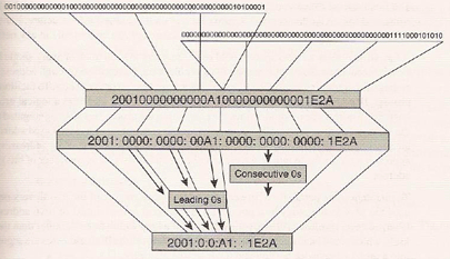
Obviously the 128bits can be represented as a succession of 0s and 1s, which in turn, in order to shorten this exaggerated size, we can represent in hexadecimal numbers until we get a succession of 32 characters. But that is still intractable for humans, so we can split this representation into 8 groups of 4 hexadecimal characters separated by colons (:). The decimal representation that was used in IPv separated by dots is not applicable to IPv6. As far as the representation of IPv6 addresses is concerned, a couple more rules are added:
- We remove the leading zeros. E.g. 00A1 -> A1
- Groups of four consecutive zeros can be skipped and we place only the group indicator, that is, the colon (:). E.g. 0000:0000:23A1 -> ::23A1
Since the (:) has always been used to separate the IP from the port, RFC 2732 suggests putting the IPv6 address between brackets to avoid confusion.

IPv6 address architecture
In RFC 3513 three types of addresses are mentioned:
- Unicast identifies a node, unicast traffic is directed to a single node.
- Multicast identifies a group of nodes, multicast traffic is directed to the nodes of the group.
- Anycast identifies a group of nodes, anycast traffic is directed to the closest node of the group.
IPv6 Unicast addresses
The most important traffic of the network is unicast, which tries to transport the information of the IP services through the network, from a source node to a destination node. In order to make groupings of nodes that can be routed, IPv4 offers us mechanisms such as addressing by subnetting. So any IPv6 IP is made up of two groups, one that indicates which network it belongs to and another that indicates which host it is. In order to keep a parallel with the way of addressing, it is done the same as in subnetting: at the end of the address a (/) is placed together with the number of bits that define the network IPs.
RFC 3513 makes it very clear that the interface ID should be: "For all unicast addresses, except those that start with the binary value 000, Interface IDs are required to be 64 bits long and to be constructed in Modified EUI-64 format". This rule aims to keep a unique ID for all network interfaces globally. To generate the interface ID it can be done in the following ways:
- Generated from the layer 2 address in "modified EUI-64" format, with this information we generate the interface ID. The 7 most significant bits of the EUI-64 define the local scope when these bits are at 0; if we find them with the value 1 the scope is global, not only local. There are different mechanisms to define each type of medium when building the interface ID in "modified EUI-64" format (I will talk about it again later on).
- RFC 3041 defines how to autogenerate the address randomly. This mechanism has been developed basically to preserve the privacy of global addresses.
- The interface ID can be obtained via DHCPv6.
- It can be configured manually.
- CGAs based on RFC 3972 through hash with a public key. This method of generating interface IDs adds a level of security and offers the ability of authentication. The Neighbor Discovery process uses CGAs.
It is important to be clear about the concept of scope, which would be something like the scope of the domain of a network, be it at a physical or logical level. Mastering the concept of scope will allow us to understand the traffic of a network better and we will be able to apply policies on that traffic in a much simpler way. It is obvious that in networks that use routable addressing, such as IP, addressing is essential and that gives even more importance to the scope to which the unicast addresses belong.
In IPv6, unicast addresses have three types of scopes defined:
- The link-local scope identifies all the hosts in a layer 2 domain. The unicast addresses used in this scope are called link-local addresses.
- The unique-local scope identifies all the discoverable devices within an administrative site or domain that typically contains different links. The unicast addresses used in this scope are called ULAs.
- The global scope identifies all the discoverable devices across the internet. The unicast addresses used in this scope are called GUAs.
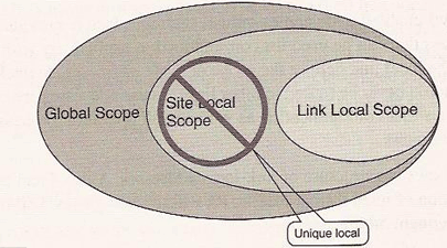
The ranges of private addresses (e.g. 10.x.y.z) currently used in the private networks of many companies is one of the important topics to comment on. The IETF working group that has defined IPv6 has defined a scope and a type of unicast addresses called unique-local, keeping the properties we already had with the private IPs of IPv4.
Link-Local Addresses
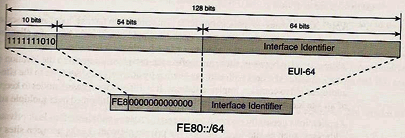
When a node of an IPv6 network starts up, each interface has a layer 3 address that can only reach the other nodes of the same link. This local link has a scope of the addresses that are connected to it, the addresses of these interfaces are called link-local addresses. In principle these addresses do not know how to get out through a gateway. At most they can discover which is the address of that gateway.
Unique Local Unicast Address (ULAs)
If what we want is to set ourselves up a private addressing, not globally routable, as we did with IPv4 with, for example, 10.x.y.z, what we have to do is refer to RFC 4193, where a scope called unique-local unicast address is defined, and the addresses of this scope, although they have to be unique for the whole internet, in order to avoid the problems that having non-unique private ranges originates in IPv4, we can still have private addressing in our networks locally. But now routable through the rest of the nodes of the internet. Therefore, we no longer have the dependency on NAT as happened in IPv4.
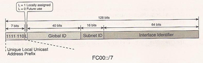
The spectrum reserved for unicast addresses of the ULA type is FC00::/7, as we can see in the previous diagram. Some comments on the elements of the diagram:
- L identifies the assignment policy. Currently only the value 1 is used (FD00::/8) informing that it is a local assignment.
- Global ID is a 40 bit identifier that ensures that the address is unique. This identifier is generated pseudo-randomly and cannot be sequential. Since ULAs should not be globally routable, they do not need to be aggregated, that is why the global IDs do not need to be sequential.
- Subnet ID the administrator of the local network assigns this value in order to organise the hierarchy of the local network.
- Interface ID has the same meaning for all unicast addresses and is 64 bits long in "modified EUI-64" format.
An important improvement as far as ULAs are concerned, compared to the previous private address system, is that now it is simpler to interconnect two isolated private networks through the internet. Since they know how to reach each other without the need for a VPN. For example, there will never be IP conflicts between two isolated private networks thanks to IPv6 addressing.
Global Unicast Address
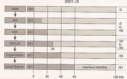
GUA addresses, as their name indicates, aim to be unique worldwide and routable. These addresses are identified with the 3 most significant bits set to the values "001" (2000::/3), as defined in RFC 3587.
Because the address space is much larger than in IPv4, in order for the routing tables not to be excessively large IPv6 is forced to establish very strict rules on the aggregation prefixes. Thanks to that, those routing tables that could worry so much about the performance of the network devices can be controlled much better. A lot of effort has been devoted to developing a flexible structure that facilitates a simple aggregation of the GUAs.
Finally RFC 3587 defines the aggregations through very rigorous policies in order to simplify the structure of the GUAs as much as possible:
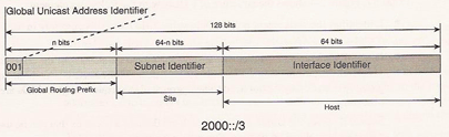
- Global routing prefix the ISP assigns a piece of its prefix assigned by IANA, and it reserves a subspace for its clients. Normally less than 48bits, the procedures to follow are commented on in RFC 3177.
- Subnet ID each organisation receives a prefix from its ISP where the global routing prefix identifies the ISP and the organisation within the ISP, and the subnet ID identifies the structure of the organisation.
- Interface ID the 64 least significant bits are used for the interface ID of the nodes of the link.
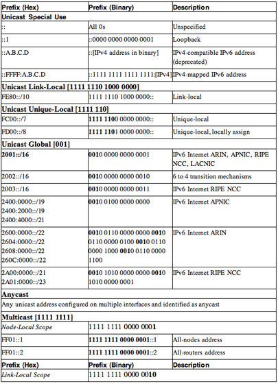
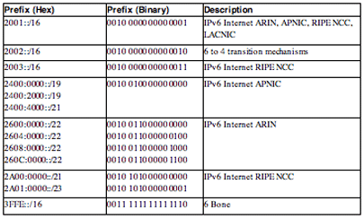
Table with the summary of the IPv6 address assignments of the ULA type at the time of writing this document:
The current RIRs are:
- African Network Information Center (AfriNIC)
- Asia Pacific Network Information Center (APNIC)
- American Registry for Internet Numbers (ARIN)
- Regional Latin-American and Caribbean IP Address Registry (LACNIC)
- Rseaux IP Europens (RIPE NCC)
The RIRs assign pieces of the prefixes they have received from IANA to the NIRs, the LIRs, or the ISPs. To make all these assignments from 32 to 35 bits are used.
Special-Use Addresses
Finally, a small group of unicast addresses has a special definition of use. They do not have an associated scope, which is why they are discussed separately from the other unicast addresses.
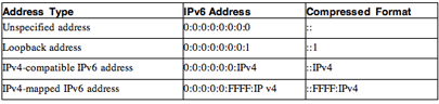
- The unspecified address is not assigned to any interfaces. However, it is used as an SA by devices that do not have an IPv6 address or their IPv6 address has not been yet proven to be unique within the local link. The unspecified IPv6 address has all 128 bits set to 0. It can be represented as 0:0:0:0:0:0:0:0, or as :: in compressed form.
- The loopback address is used by every node to refer to itself, and it is similar to the 127.0.0.1 address in IPv4. In IPv6, the loopback address has all the 127 leading bits set to 0, and the last bit is 1. It can be represented as 0:0:0:0:0:0:0:1, or as ::1 in compressed form.
The other two special types of addresses are related to the coexistence between IPv4 and IPv6. When linking the two address spaces it is very important to support the coexistence of these two address spaces. So two mechanisms have been developed to keep the relationships between IPv4 and IPv6 addresses:
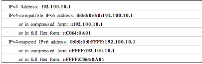
- The IPv4-compatible IPv6 address was defined to be used for dynamic tunneling and is built by adding the IPv4 address to 96 bits set to 0. This address type was deprecated and it is no longer used.
- The IPv4-mapped IPv6 address is used to represent the address of an IPv4 node in an IPv6 format. The IPv4-mapped IPv6 address is built by adding the IPv4 address to 80 bits set to 0 followed by 16 bits set to 1.
Example: the IPv4 192.168.10.1 with its IPv6 correspondences according to the IPv4-compatible and IPv4-mapped system.
IPv6 Anycast Addresses
When a unicast address is assigned to multiple interfaces, typically belonging to different nodes, that becomes an anycast address and it is specified in RFC 3513. Anycast and unicast addresses cannot be distinguished, so the node has to be told that its unicast address is of the anycast type. A packet of the anycast type will be delivered to the closest unicast destination address it finds. An anycast address cannot be used as a source address. Often this resource, anycast, is used to replicate very important services within a network, such as DNS, web servers, etc.
The anycast address of the subnet router is defined in RFC 3513 for each prefix as the address with the interface ID at '0'. A router has to support the anycast address of the subnet router for all the prefixes configured on its interfaces. A packet directed to any of the interfaces will have to be delivered to the closest router that has an interface with that prefix.
RFC 2526 defines an additional set of anycast addresses reserved given a prefix. Next we can see the structure of the anycast addresses.
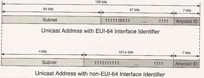
The format of the addresses makes clear the attempt to reserve part of the addresses of a subnet to use them as anycast. That was done to avoid possible conflicts with other reserved addresses. The anycast ID field of the previous diagram can take the following values: 0 to 125 and 127 (00-7D, 7F) are reserved; ID 126 (7E) is the only one in use for the anycast addresses of the home agents of MIPv6.
Note: MIPv6 provides a host with a mechanism to discover the address of one of his home agents (HAs). The host can attempt to register to the home agent's anycast address (described in this section) hosting its home prefix. One of the HAs will receive the request, reject the registration, and instead reply to the host with a list of the actual addresses of the HAs it can use.
IPv6 Multicast Addresses
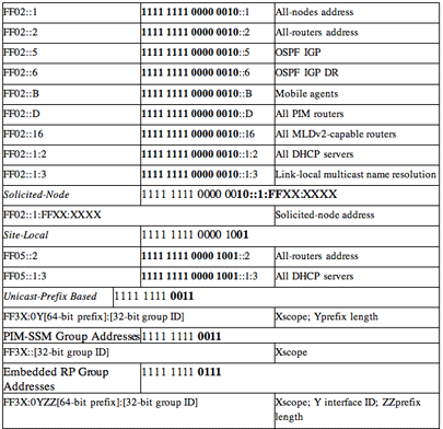
A multicast address identifies a group of interfaces. A packet with a multicast destination address will be delivered to all the members of the group. We must also remember that a multicast address can never be a source. A multicast address has its 8 most significant bits with the value 1 (FF00::/8) as we can see in the following diagram.
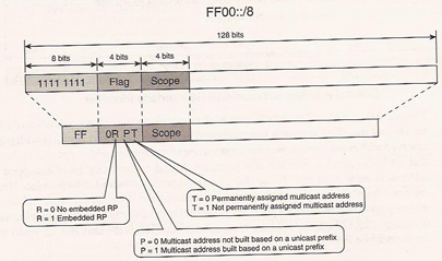
Three of the four bits in the flag are currently in use:
- The least significant bit "T" defined in RFC 3513 always has the value 0 for the multicast addresses assigned by IANA. If it has the value 1, it refers to multicast addresses not permanently assigned.
- The "P" bit defined in RFC 3306, indicates that a multicast address is based (1) or not (0) on a unicast address.
- The "R" bit defined in RFC 3956, if it has the value 1 it indicates that it contains unicast addresses of the RP (multicast rendezvous points) type in the address group it contains.
The 4th missing bit is reserved for future uses and currently it is always left fixed at 0. The "P" bit indicates that a multicast address is built on the basis of a unicast address; because a unicast address is considered to have a limited lifetime, therefore, a multicast address of this type cannot be permanent. That means that the "P" bit with value 1 requires the "T" bit to have value 1 as well.
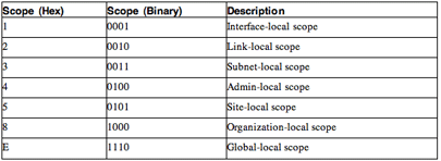
Scoping is a powerful feature built into the multicast addresses of IPv6. It provides the routers with the necessary information to transport the multicast traffic to the right domain. Next we can see a table with the possible values of the 4 bits.
Unicast-Prefix-Based Multicast Addresses
The GLOP addresses that were introduced in IPv4 in order to create global and unique multicast addresses for organisations that had ASNs. The addresses were built on the basis of the global and unique ASNs. RFC 3306 extends this concept and defines a mechanism that generates global IPv6 multicast addresses based on a unicast prefix as we can see in the following diagram.
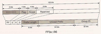
The reserved bits are set to 0 (the 64 bits of the unicast prefix field). For example, next we can see the multicast address of the unicast address 2001:100:abc:1::/64.

Note: The scope of the unicast address based on the prefix should not exceed that of the embedded unicast prefix.
Solicited-Node Multicast Addresses
From the layer 3 unicast address, thanks to this mechanism we can know the local link address (the MAC). The format of the address FF02::1:FF00:0000/104, where the 24 least significant bits are the same for the unicast and anycast addresses that generated them. That represents a deterministic method to identify the group of local multicast links on which a host with an IPv6 unicast address is listening. If that cannot be determined then this multicast information has to be sent to the address of the solicited-node multicast.
IPv6 and Layer 2 Addressing
IPv6 addresses have two correlations with layer 2 addresses. The first, IPv6 is capable of generating an interface ID from a layer 2 address. The second is common with IPv4, it provides a mechanism to map multicast IP addresses with the multicast addresses of layer 2.
EUI-64 Interface Identifiers
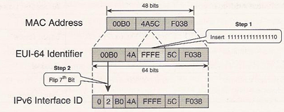
IEEE specified the format of EUI-64 identifiers. To make an IPv6 interface ID identifier, the only thing that has to be done is to move the sixth bit in standard internet order (universal/local bit).
IEEE also specified a mechanism to generate a 64bit identifier (EUI-64) from the 48 bits of the layer 2 address. With this mechanism we can establish a correlation between the MAC addresses and the interface IDs as part of the IPv6 address. Next we can see an example of how an interface ID is generated from a MAC. First the EUI-64 identifier has to be created and then we modify it to create the interface ID.
IPv6 Addressing Architecture at a Glance