SPI - Serial Peripheral Interface
Translation of the original in Catalan. Read it in: CatalàCastellano
When I talked about GPIO I talked about this protocol that can run on ports of this type. Well here you have a small definition of what this protocol does and how it works. A place where we can often find SPI buses are PDAs and mobile phones.
Definition
The SPI bus is serial and synchronous, it uses 4 cables and is used in many peripheral microprocessors. Ports with SPI support handle a medium/low bandwidth (1 megabaud) between their CPUs and the other devices that may be connected to the bus.
How it works
The SPI bus is relatively simple to implement for slow external devices and we don't need many cables to establish communication. The interface of this bus was defined by Motorola in the MC68HCxx microcontroller standard. It uses a clock to mark the synchronism of the data line both for input and output of the microcontroller and the information moves in blocks of 8 bits.
The SPI bus uses a master/slave interface, as is normal in synchronous serial communications it is the master that marks the clock. An interesting fact about this kind of bus is that we can receive and send information from the devices simultaneously, so it is a full-duplex protocol.
A bit further inside
The signals the bus uses are:
- SLCK serial clock, always controlled by the master
- MISO master-in slave-out data
- MOSI master-out slave-in data
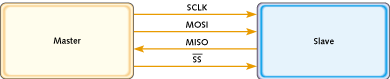
In a normal application we will have to connect the SCLK output of the microcontroller to the SLCK input of the converter. The MISO to the DOUT pin of the converter, the MOSI to the DIN pin. Each IC (integrated circuit) on the SPI bus has a CS (chip-select) signal, the signal has to be activated in order to enable the device on the bus. To do this we can use any of the standard output lines of the microcontroller. We do have to think, though, that if we have n ICs connected to the bus, we'll need n signals to activate the ICs. Also if we share the clock signal and the data lines we will have to enable the corresponding CS signal in each case.
Assessment
As you can see the design of the bus and the protocol of use are very simple. So much so that if we use too many devices connected to the same data line the whole thing becomes a bit heavy to deal with. Despite that, for a great many applications it's a good idea to use it.
Example of use
The people at maxim have a technical document (local) that is very good, where in a few lines they explain how to communicate with a digital thermometer, specifically the DS1620, with only 3 cables through an SPI bus. The diagram of the system is fairly simple and gives you an idea of the simplicity of connecting this temperature sensor to the SPI bus.