Accessing the proprietary registers of an Omnivision CMOS through the USB 2.0 interface - The source code
Translation of the original in Catalan. Read it in: CatalàCastellano
So that what I say doesn't sound so much like Japanese I'll try to explain it in parts. It's about doing what I proposed in the article: Problema amb OVTDTool: Omnivision 2610 ECX. That is, we have a development kit for the Omnivision OV2610 camera which carries a CMOS image sensor and a Cypress chip that communicates the CMOS sensor with the PC through a USB 2.0 interface. So in order to access the proprietary registers of the CMOS it has to be done using 'usb vendor requests'. That is, sending 'request' packets to the USB chip indicating that we want to access proprietary registers of the CMOS. When I talk about proprietary registers what I mean is that they are not standard USB 2.0 registers but rather specific to the manufacturer for this product.
In this case what this lets us do is enable/disable auto-adjustment functions: AGC (auto gain control), AWB (auto white balance), etc. we can also do other things like fixing parameters that by default have other values, such as brightness, contrast, RGB colour components, etc. That is, we can make the camera (CMOS sensor) work the way we're interested in.
A bit of theory to know what we have to do
In order to understand how USB technology works if you don't want to buy a book there's a website that explains it in an extraordinary way: USB in a NutShell ( pdf ). There you'll be able to see that there are some logical elements inside USB devices that are called ENDPOINTS specifically there's a type of ENDPOINTS that are called "Control Transfers" these are the ones used to send configuration commands. Functionality of the ENDPOINT of CONTROL TRANSFER type would be:
Control transfers are typically used for command and status operations. They are essential to set up a USB device with all enumeration functions being performed using control transfers. They are typically bursty, random packets which are initiated by the host and use best effort delivery. The packet length of control transfers in low speed devices must be 8 bytes, high speed devices allow a packet size of 8, 16, 32 or 64 bytes and full speed devices must have a packet size of 64 bytes.
So these are the lowest level packets that we have to generate to configure the device. Since what we want is not to complicate our lives so much what we do is try to generate these packets from higher layers and so not go down so many levels into problems that aren't ours. For example, retransmissions, reception acknowledgements, sending window control, etc. Therefore, what we'll be interested in is the concept of "USB Descriptors":
All USB devices have a hierarchy of descriptors which describe to the host information such as what the device is, who makes it, what version of USB it supports, how many ways it can be configured, the number of endpoints and their types etc
Specifically the descriptors are organised according to the following hierarchy:
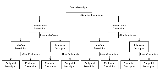
As we can observe in the graph the descriptor we're interested in is the "Endpoint Descriptor" which are the ones that let us access the CONTROL TRANSFERs I mentioned before. If we look at the data structure that defines an ENDPOINT DESCRIPTOR we can observe that it has an 8-bit field called "bmAttributes" in this field the first two bits let us define the "Transfer Type" and from here we can extract that the value we're interested in is "00" for these two bits, that is, "CONTROL". With this we'll be telling the packet to be of the CONTROL TRANSFER type when it leaves the ENDPOINT.
In order to configure our packet we have no choice but to keep climbing the stack until we reach the "Setup packets":
Every USB device must respond to setup packets on the default pipe. The setup packets are used for detection and configuration of the device and carry out common functions such as setting the USB device’s address, requesting a device descriptor or checking the status of a endpoint.
And here we have what we wanted, the format of the packet we really want to send as we can see it's a very simple packet of only 8 bytes, which we have to configure bit by bit. The first 8-bit field: bmRequestType serves to define the type of request we're going to make, these 8 bits are divided into 3 groups and we have to choose the appropriate bit groups for our request. That is:
- 1st group: Data Phase Transfer Direction (1bit) 0 Host to device and 1 Device to Host
- 2nd group: Type (2 bits) 00 Standard, 01 Class, 10 Vendor, 11 reserved. For our case what interests us would be 10 Vendor, because we want to access registers that aren't standard USB but proprietary to the CMOS manufacturer.
- 3rd group: Recipient (5 bits) 00000 Device, 00001 Interface, 00010 Endpoint, 00011 Ohter, the rest are reserved. For our case what interests us is 00000 Device.
Up to here we have the first 8 bits defined, that is: 0xc0 (11000000) 'we read' from the device and 0x40 (1000000) 'we write' to the device. These would be the values to remember. The other 4 fields:
- bRequest (8bits) we'll put the register with value 0x2 to write and with value 0x3 to read. You need to check your product's datasheet to know exactly what you want to put in this field, since this, as I've already said, are manufacturer-specific commands.
- wValue (16bits) here we'll put the value we want the register we want to write to have.
- wIndex (16bits) we indicate the register we want to access, whether to write or to read
- wLength (16bits) length of the message we want to receive when we read. Normally 8 or 16 bits. They tend to be fixed values, when we're talking about vendor proprietary registers.
Up to here the theory. Everything seems very confusing therefore, I take the opportunity to recommend again reading and deeply understanding the document I've referenced. I've explained all this because otherwise it would be impossible to understand what we really want to do. Since in practice everything ends up summarised in a few lines of code.
Practical goal
Since we already know what we want to do, now we only need to know how we have to do it. The first thing we need is to make a program that lets us access the device directly at a low level and gives us a user-level interface to access the specific functions this is called a driver. Something we don't seem too interested in doing because we already have a driver and it already works well enough, it's not about reprogramming it. So since we don't have the user space functions of our driver documented it falls short for us. What we could do is program a filter driver, these only work on NT-based architectures (2K, XP and 2k3) what they do is place themselves on top of the existing driver and change its behaviour only in some aspects and when some user space application requires it, so for the other applications they are transparent and these can work with the native driver without problems.
Obviously this can also mean a huge amount of work and even more for someone who doesn't master M$'s DDK (Device Drivers Kit) and the WDM (Windows Driver Model) architecture. But I've found a user space library to access USB devices in a generic way and what's more this one implements a filter driver that can be installed on top of the device's generic driver. This lets us program whatever we want with 4 lines and have the manufacturer's generic driver with which all the programs available for it work.
For our problem we only have to write 4 lines in C invoking the library I named and it itself takes care of working against the filter driver. Also we have the API of this library completely specified. If all this seems little to you I can tell you that it's based on a multiplatform Unix project and that the code is 100% portable with very few modifications. Also with a GPL licence, of course. So here you have the great discovery libusb-win32. By default you'll see it comes with an application that discovers the USB devices connected to our system. It's a good example to start getting familiar with how to use the library.
NOTE: libusb-win32 also let us create user space drivers and not only work with filter drivers, we only have to program our code using the generic driver API they implement.
How to work with libusb-win32
The first thing you have to do is download this libusb-win32-filter-bin-0.1.10.1.exe (local) and install it with no USB device connected to the system, if possible. What this will do is install the filter driver, if you don't see it relax it's not trivial, -bear in mind that it's not a driver but rather sits on top of it- and 3 .lib files one to use through the GCC compiler, another for the Borland compiler (BCC) and finally for Visual Studio (MSVC). The last case has been my case. It also installs a file called usb.h which is the one we have to use to compile our program and not the usb.h that the DDK brings. So be careful when defining the dependencies of the MSVC compiler and linker.
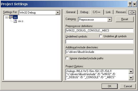
I've installed the package in c:\drivers\libusb, I mention this because next I'm showing you some screenshots of how I've modified the MSVC project 'settings' so that it's able to compile and link my program.
Inside MSVC if we go to Project -> Settings:
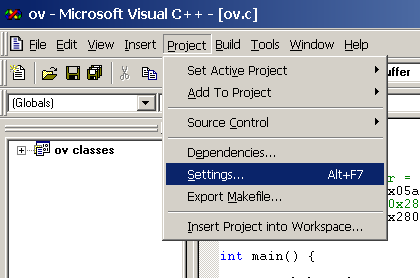
We can define the special includes of our project, necessary for the compilation process:
And the libraries to use in the linking process:
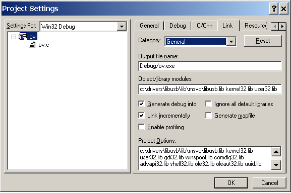
Now we're able to make a program that works with libusb-win32, we only have to add #include <usb.h> at the beginning of our code and enjoy the libusb API.
Let's put the theory into practice
In a few words let's write the code I needed, after so much story. Let's go step by step, the first thing to do is know how to initialise the device and look for the USB devices connected to the system:
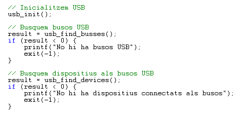
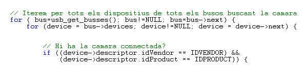
Once we have the list of USB devices connected to the system we iterate through them looking for our camera. Since I don't expect to have more than one camera connected to the same computer I haven't taken it into account in the code. What I've done is take a USB bus analysis application and discover the manufacturer identifier (idVendor) and the product identifier (idProduct). In my case: idVendor = 0x05a9 (Omnvision) and idProduct = 0x2800 (OV2610). So we look for this:
Once we've identified our device the time comes to put into practice everything we had learned a while ago. So let's build our control packets (setup packets) that access the manufacturer's own registers. In this example what I do is access register number 0x13 and save its value in the buffer, then I show it on screen. Then we modify the value of register 0x13 and give it the value 0x15 next we read it again and show it on screen to check that it has changed value.
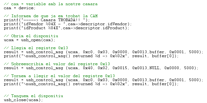
To know what's in each register, what values it can have and what they mean, you have to look it up in each manufacturer's documentation. In my case I found this in the Omnivision CMOS datasheet which is one of the few things the manufacturer gave us when buying the 'development kit'.
I've commented the code a lot therefore, I consider that it's more than clear how it works. If you want to download it: ov.c. If you want the executable directly to try it: ov.exe, although I doubt it'll be of any use to you since this .exe only works with the development kit I've used.
The program output is the following:
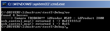
We can check how the previous value of register 0x13 is 0xcf and how our program changes the value to 0x15, so. IT WORKS!!!
Conclusions
You can check how all the initial theory 'stuff' serves to understand how we have to form the usb_vendor_msg() requests of the libusb-win32 library. Without understanding how the USB architecture works in depth it was impossible to know how these requests had to be formed. In fact, I have to confess that what I did was apply reverse engineering since I had a debugging tool for the product (OVTDTool.exe) that let me access these registers and then thanks to a driver creation wizard -Jungo- I was able to put into practice the theory I've explained. The problem was that this software didn't let me create filter drivers that would work with the driver I already had for the camera and forced me to create my own driver from 0.
So, big problems big solutions and after continuing my training I discovered this great invention of the 'filter drivers' and the one that finally made me see the light was the libusb-win32 library which has let me in very little time find the way out of this 'apparently complicated problem'. Now it can be seen that it wasn't so much.